- 您现在的位置:买卖IC网 > Sheet目录218 > CUB5RTR0 (Red Lion Controls)RTD METER REFLECTIVE
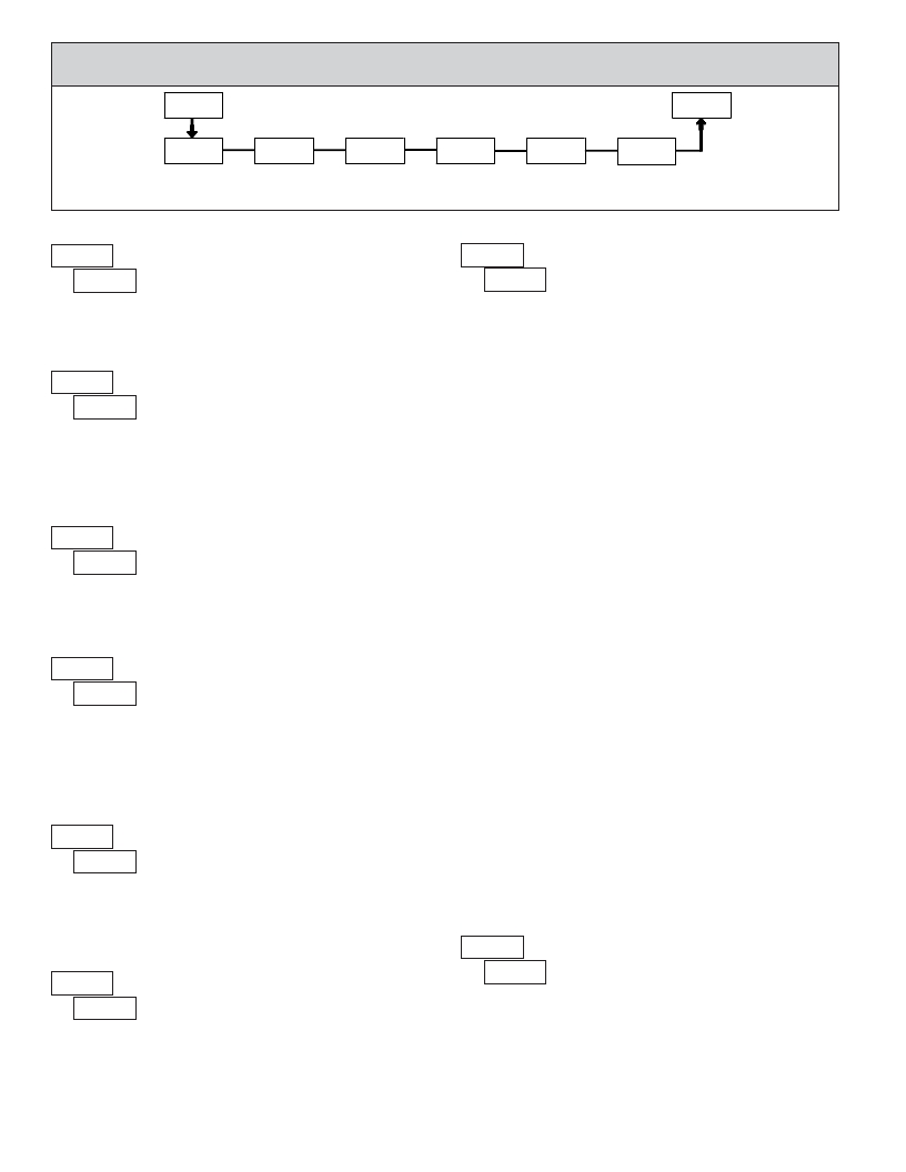
6.2 MODULE 2 - S ECONDARY F UNCTION P ARAMETERS ( 2-SEC )
2-SEC
SEL
PARAMETER MENU
Pro
HI-En
Max Display
Enable
HI-t
Max Capture
Delay Time
LO-En
Min Display
Enable
LO-t
Min Capture
Delay TIme
FCS
Factory
Service
CodE
Access Code
For Service
MAX DISPLAY ENABLE
Operations
Operations
CALIBRATION
HI-En ?
NO YES
? NO
Enables the Maximum Display Capture capability.
CodE
?
?
48
The CUB5RT uses stored resistance calibration values
to provide accurate temperature measurements. Over
time, the electrical characteristics of the components
inside the meter could slowly change. The result is that
the stored calibration values may no longer accurately
define the input circuit. For most applications, recalibration every 1 to 2 years
should be sufficient.
HI-t ? 0.0
LO-En ?
MAX CAPTURE DELAY TIME
to 999.9 seconds
? 2.0
When the Input Display is above the present MAX value for the entered
delay time, the meter will capture that display value as the new MAX reading.
A delay time helps to avoid false captures of sudden short spikes.
MIN DISPLAY ENABLE
NO YES
? NO
Enables the Minimum Display Capture capability.
MIN CAPTURE DELAY TIME
Calibration of the CUB5RT involves a resistance calibration. Allow 30
minute warm up before performing any calibration related procedure. The
following procedures should be performed at an ambient temperature of 15 to
35 °C (59 to 95 °F).
Calibration should only be performed by individuals experienced in
calibrating electronic equipment.
CAUTION : The accuracy of the calibration equipment will directly affect the
accuracy of the CUB5RT.
10 OHM RTD Range Calibration
1. Set the Input Range Jumper to 10 ohm.
2. With the display at CodE 48 , press and hold the SEL button for 2 seconds. Unit
will display CAL NO .
3. Press the RST button. Display reads CAL r10 .
4. Press the SEL button. Display reads 00r .
5. Apply a direct short to terminals INP+, EXC, and COMM using a three wire
link. Press SEL . Display reads CALC for about 15 seconds.
6. When the display reads 15.0r , apply a precision resistance of 15 ohms (with an
accuracy of 0.01% or better) to terminals INP+, EXC, and COMM using a
three wire link. Press SEL . Display reads CALC for about 15 seconds.
7. When display reads CAL NO , press the SEL button to exit calibration, or
proceed to the 100 ohm RTD Range Claibration.
LO-t
?
?
2.0
0.0
to
999.9 seconds
100 OHM RTD Range Calibration
1. Set the Input Range Jumper to 100 ohm.
When the Input Display is below the present MIN value for the entered delay
time, the meter will capture that display value as the new MIN reading. A delay
time helps to avoid false captures of sudden short spikes.
FACTORY SERVICE OPERATIONS
2. With the display at CodE 48 , press and hold the SEL button for 2 seconds. Unit
will display CAL NO .
3. Press the RST button until the display reads CAL r100 .
4. Press the SEL button. Display reads 0.0r .
5. Apply a direct short to terminals INP+, EXC, and COMM using a three wire
link. Press SEL . Display reads CALC for about 15 seconds.
6. When the display reads 300.0r , apply a precision resistance of 300 ohms (with
an accuracy of 0.01% or better) to terminals INP+, EXC, and COMM using
FCS
?
?
NO
NO
yES
a three wire link. Press SEL . Display reads CALC for about 15 seconds.
7. When display reads CAL NO , press the SEL button to exit calibration.
Select YES to perform any of the Factory Service Operations shown below.
RESISTANCE DISPLAY MODE
CodE ?
?
?
CodE
? 85
RESTORE FACTORY DEFAULT SETTINGS
Entering Code 66 will overwrite all user settings with
the factory settings. The meter will display rESEt and then
66 return to CodE 00 . Press SEL button to exit the module.
Pressing both the SEL and the RST button on power-up
will also load the factory settings and display rESEt . This allows operation in
the event of a memory failure or corruted data.
8
Entering Code 85 will place the CUB5RT in a resistance
display mode. This mode is useful for diagnostic purposes
before and after calibration, or to display the measured
resistance of a connected RTD probe. If the RTD type is set
for Cu427 with the jumper set to the 10 ohm position, the display will read
resistance in 0.000 ohms resolution. For all other RTD types, with the jumper in
the 100 ohm position, the display will read in 0.00 ohms resolution.
Re-entering code 85 toggles the display back to the temperature display mode
without having to remove power from the meter. If power is removed, the
display always returns to the temperature display mode when power is reapplied.
发布紧急采购,3分钟左右您将得到回复。
相关PDF资料
CUB5TCB0
METER PANEL LCD THERMOCOUPLE RED
CUB5USB0
USB OPTION CARD
CUB5VR00
METER LCD DC VOLT 8DIGIT
CUR-3285-MB
BOX ABS 8.25X5.15X3.13" BLACK
CUR-3286-MB
BOX ABS 10.15X6.15X3.13" BLACK
CUR-793-MB
BOX ABS 4.1" X 2.23" X 2" W/BKTS
CUSTOM BGA
CUSTOM BGA SOCKETS
CW2500
EPOXY OVERCOAT 0.26OZ
相关代理商/技术参数
CUB5SNK0
功能描述:DUAL SINKING OPEN OC OUT CARD RoHS:是 类别:工业控制,仪表 >> 仪表 - 面板,数字 系列:* 标准包装:12 系列:* 其它名称:Q7072030
CUB5TB00
功能描述:TIMER & CYCLE COUNTER W/BKLT RoHS:是 类别:工业控制,仪表 >> 计数器 系列:* 其它有关文件:Declaration of Conformity 标准包装:1 系列:99766 计数速率:25Hz 数字/字母数:5 输入类型:机电式脉冲 输出类型:- 电源电压:24V 显示器类型:十进制拨轮
CUB5TCB0
功能描述:METER PANEL LCD THERMOCOUPLE RED RoHS:是 类别:工业控制,仪表 >> 仪表 - 面板,数字 系列:CUB5 标准包装:12 系列:* 其它名称:Q7072030
CUB5TCR0
功能描述:THERMO METER REFLECTIVE RoHS:是 类别:工业控制,仪表 >> 仪表 - 面板,数字 系列:* 标准包装:12 系列:* 其它名称:Q7072030
CUB5TR00
制造商:Red Lion Controls 功能描述:PRESET TIMR & CYCLE COUNTR W/REFL DSPLY 制造商:Red Lion Controls 功能描述:TIMER, ELECTRONIC , 8DIGIT, 9V TO 28V; Supply Voltage Range:9V DC to 28V DC; Panel Cutout Height:39.1mm; Panel Cutout Width:74.9mm; Time Range:- ;RoHS Compliant: Yes
CUB5USB0
功能描述:USB OPTION CARD RoHS:是 类别:工业控制,仪表 >> 仪表 - 面板,数字 系列:* 标准包装:12 系列:* 其它名称:Q7072030
CUB5VB00
功能描述:DC VOLTMETER RED/GREEN BKLT RoHS:是 类别:工业控制,仪表 >> 仪表 - 面板,数字 系列:* 标准包装:12 系列:* 其它名称:Q7072030
CUB5VR00
功能描述:METER LCD DC VOLT 8DIGIT RoHS:是 类别:工业控制,仪表 >> 仪表 - 面板,数字 系列:* 标准包装:12 系列:* 其它名称:Q7072030